The cutting head is one of the most crucial parts of any water jet cutting machine. However, it’s also a component with several consumable parts that need to be replaced periodically to keep the system at peak performance while maintaining safety standards.
You’ve made a significant investment if you’re currently using a water jet cutting system. Make the additional investment to keep the various components in working order. In part 5 of our water jet pump maintenance series, we’ll go through disassembling, repairing, and/or replacing the OmniJet III cutting head.
Check out the full video guide to rebuilding the OmniJet III by clicking the video below:
What is an OmniJet III Cutting Head?
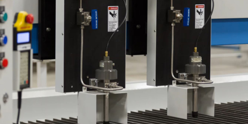
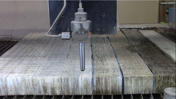
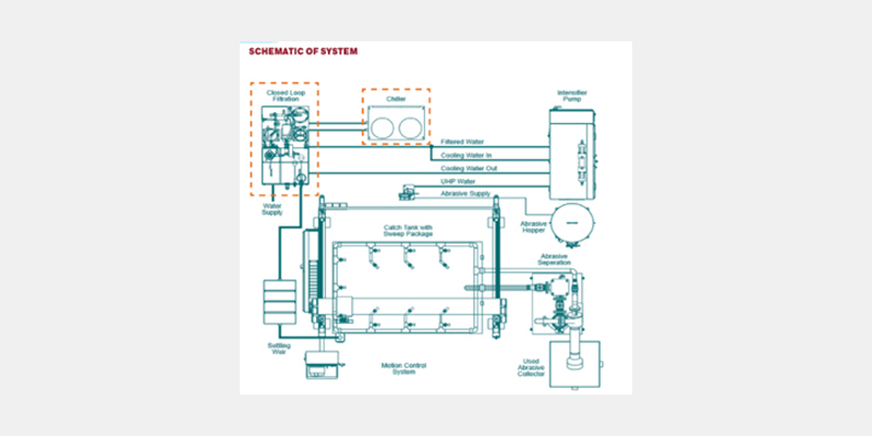
The OmniJet III is a cutting head system for turning the high-pressure water flow on and off during the cutting process and controlling the flow of water or garnet/water abrasive through the nozzle and orifice. The cutting head of any water jet machine is a critical component and one that needs to be serviced and some parts replaced from time to time in order to keep the machine running at peak performance.
When Do the OmniJet III Cutting Head Components Need to be Repaired/Replaced?
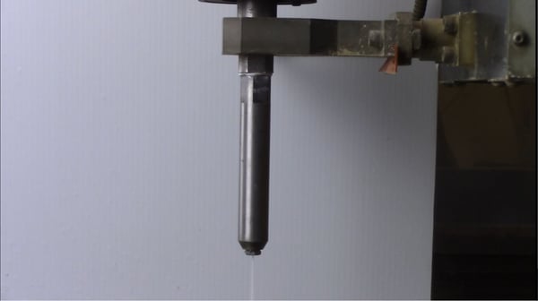
In order to service OmniJet III cutting heads, they need to be disassembled, cleaned, parts replaced (if needed), and rebuilt. The OmniJet III needs to be rebuilt when there is water leaking through the orifice and/or nozzle while the tool is turned off.
The OmniJet has a needle seat that needs to be replaced when leaking. A leaking needle seat greatly increases the chance of injury while using the system and should be replaced immediately.
Replacing/Rebuilding/Repairing the OmniJet III Cutting Head
Tools Needed
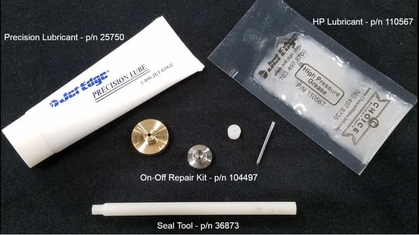
The following tools are needed to complete this repair:
- Precision lubricant (part #25750)
- HP lubricant (part #110567)
- On-off repair kit (part #104497)
- Seal tool (part #36873)
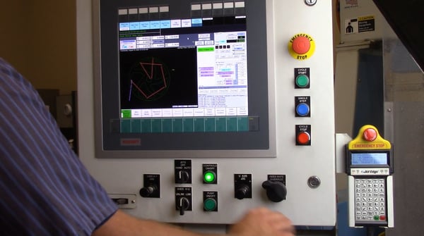
Prepping the System
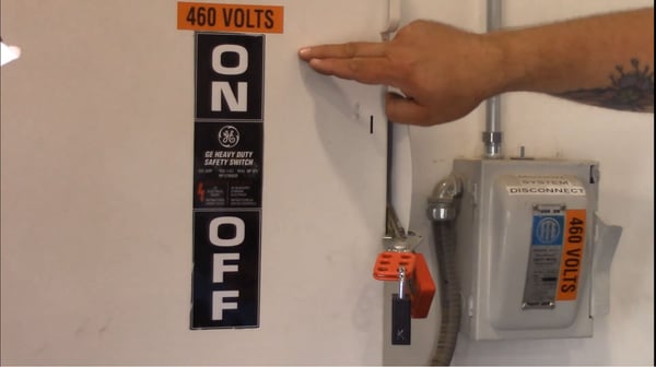
- Turn the intensifier pump off and lock out the pump.
- Move the carriage to an easily accessible location.
- If your machine has a hand valve, turn it clockwise until it stops. This turns off the water flow to the head.
- Verify that there is no pressure in the high-pressure water gauge.
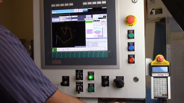
- On the machine controls, click on the “configure jet stream” on the top middle of the display. Enable only the water jet you will be repairing and disable the rest of the water jets and abrasive.
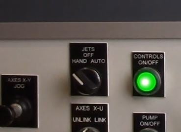
- Turn the “hand/off/auto” switch to hand and use the pushbuttons on the top of the screen to enable air to the OmniJet.
- Verify that there is no water coming from the cutting head. If no water is coming from the head, the OmniJet is now safe to work on.
Repairing and/or Rebuilding the OmniJet III Cutting Head
NOTE: The following instructions are for systems that are using Permalign abrasive heads (unless otherwise specifically noted to be water-only systems).
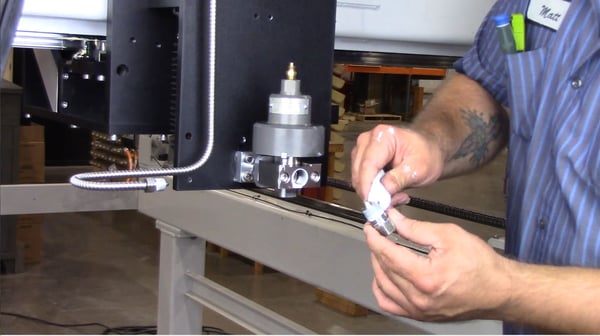
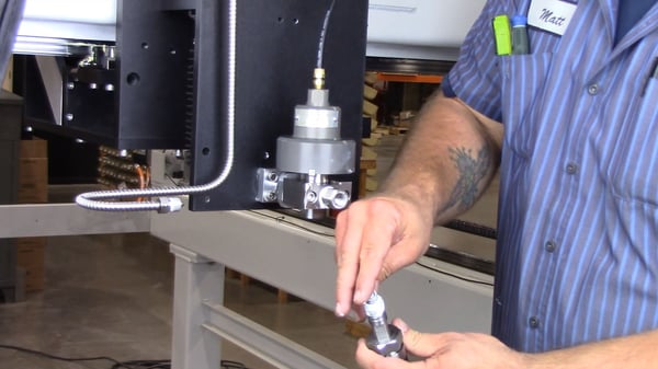
- Remove the abrasive inlet tubing.
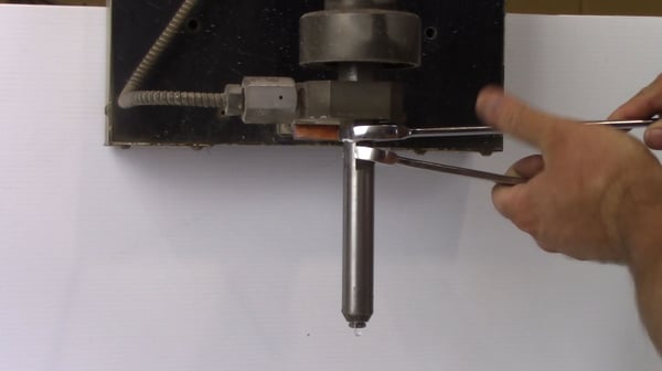
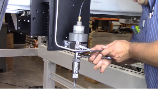
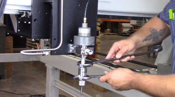
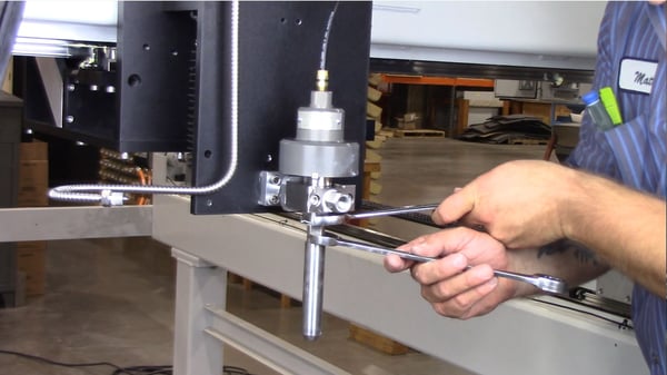
- Using a 1 1/8th and a 1 5/16th wrench, loosen the nut on the Permalign abrasive head.
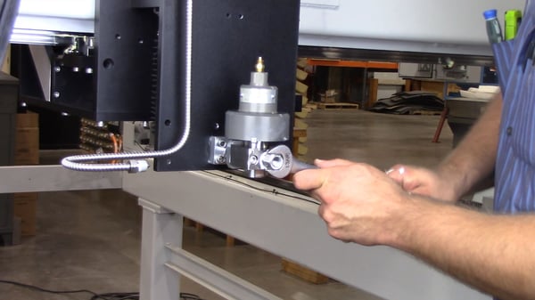
- Using a 1-inch and 5/8th wrench, loosen the adapter to the valve body and remove. Verify that the seat is removed with the adapter.
- IF USING A WATER ONLY MOUNT - You will need a 1-inch wrench and a 3/4th inch wrench.
- NOTE: if the seat stays in the valve body, remove using a finger or a plastic dowel.
- You can now turn the air supply to the head off.
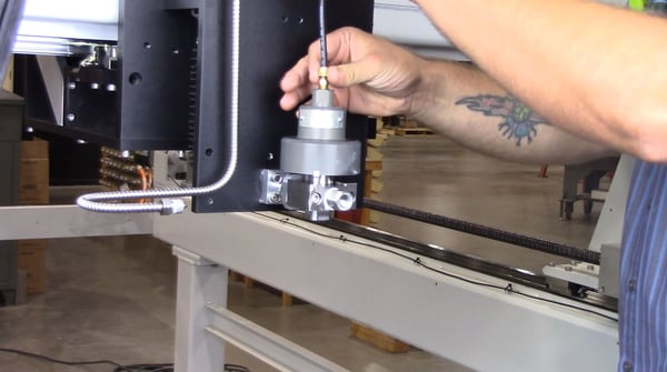
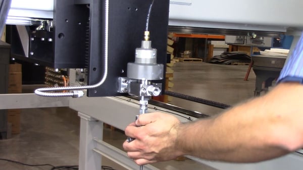
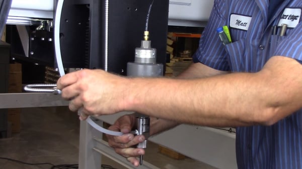
- Remove the air line in the top of the OmniJet.
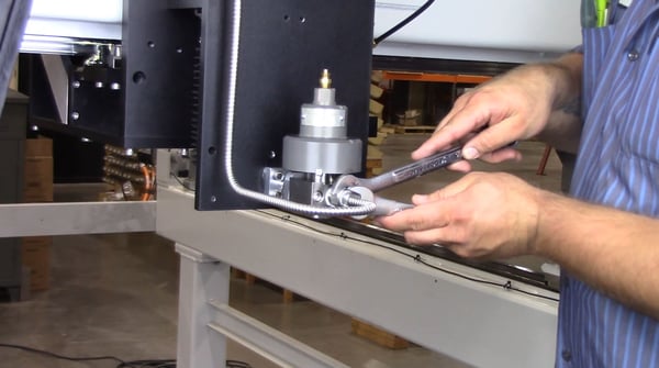
- Loosen the high-pressure line going to the inlet adapter using a 13/16th inch and 5/8th inch wrenches.
- NOTE: different high pressure tubing configurations can differ machine to machine. If you’re unsure about your model contact the manufacturer before performing this step.
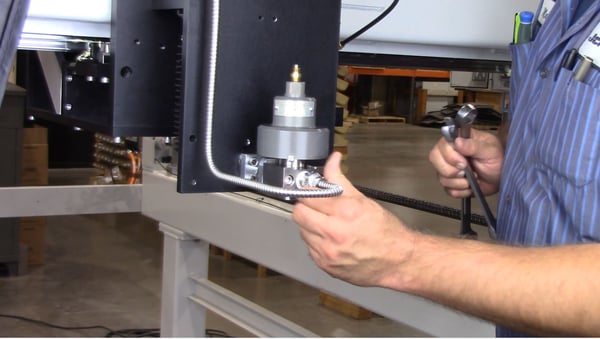
- Remove the line and cap the end so debris does not enter.
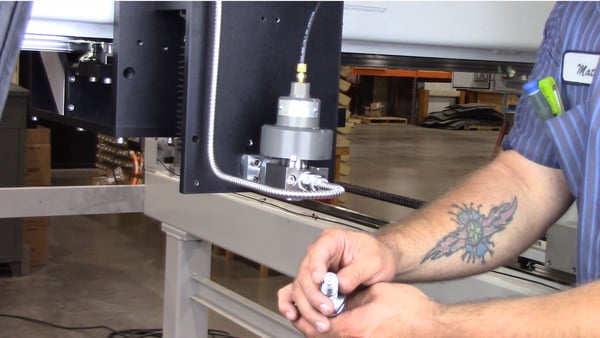
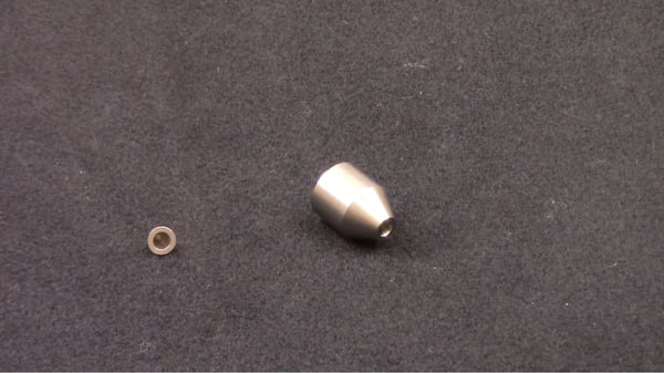
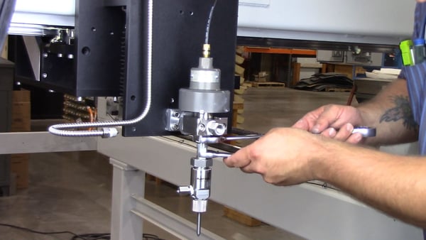
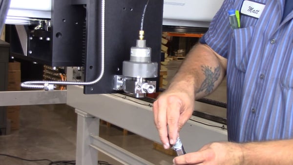
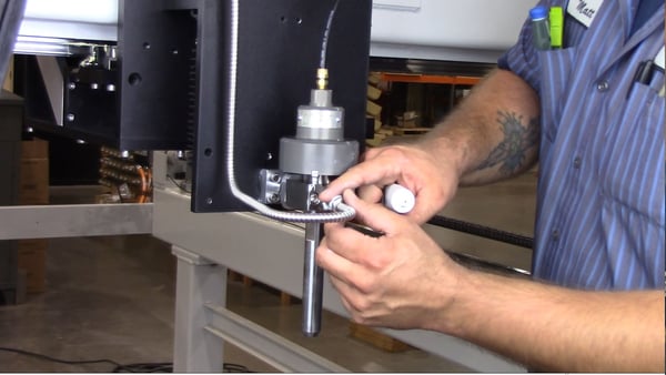
- Loosen the inlet adapter from the mounting collar and inspect the replaceable cone insert.
- If necessary, remove, inspect, clean, or replace the short stop filter.
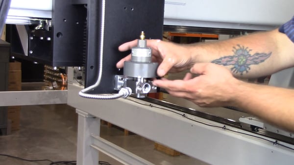
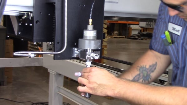
- Remove the OmniJet from the mounting collar.
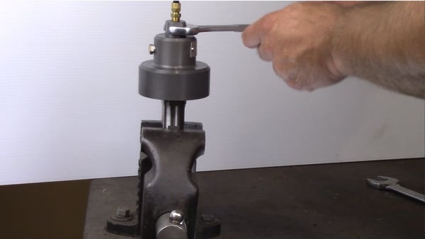
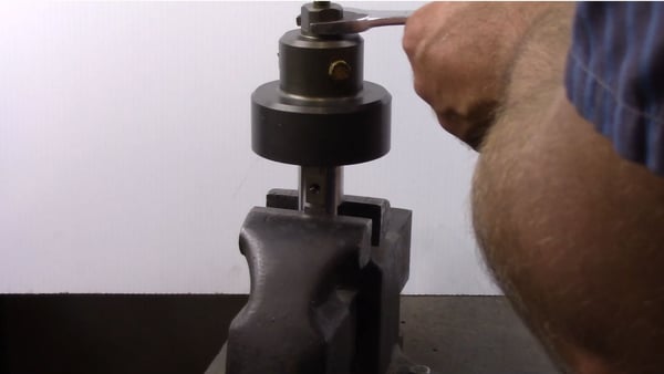
- On the workbench use a 7/8-inch wrench on the air valve and a 1-inch wrench to remove the valve body.
- NOTE: You can also place the bottom flats of the valve body into a vice to remove the air valve.
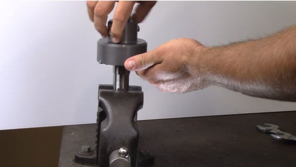
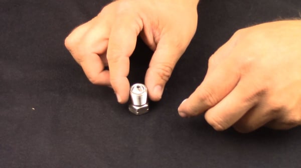
- Insert the small end of the seal tool into the outlet end of the valve body and press the needle, bearing, and seal out of the valve body.
- NOTE: effort is needed to push the components out.
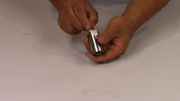
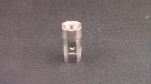
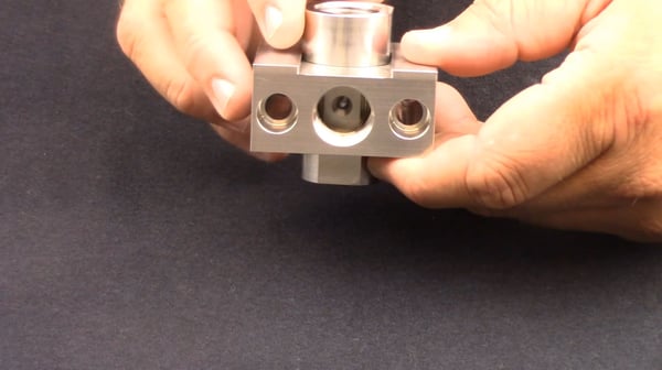
- Clean the valve body and inspect for repair.
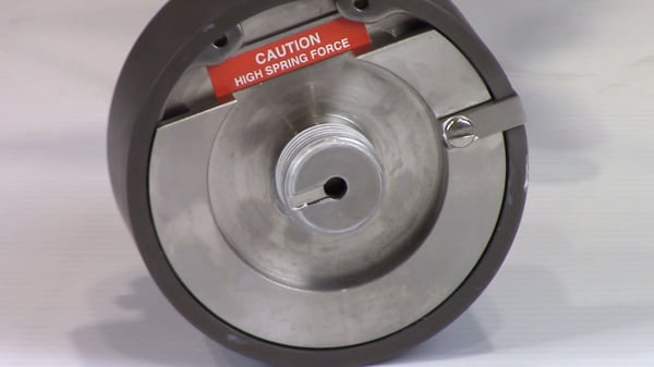
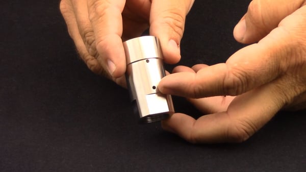
- NOTE: the location of the weep hole that is leaking will tell you where the issue is
- If the leak is coming out the top weep hole, the high-pressure seal has failed.
- If the leaking is coming from the bottom weep hole or the threads of the orifice adapter, the connection point between the seat, the mount or valve body is the issue.
- Common assemblies:
- If your issue is with the high-pressure seal and it needs to be replaced, follow steps 8-15 in our bleed down repair guide here:
- NOTE: To fully take advantage of the locking valve body, the appropriate collar must be utilized.
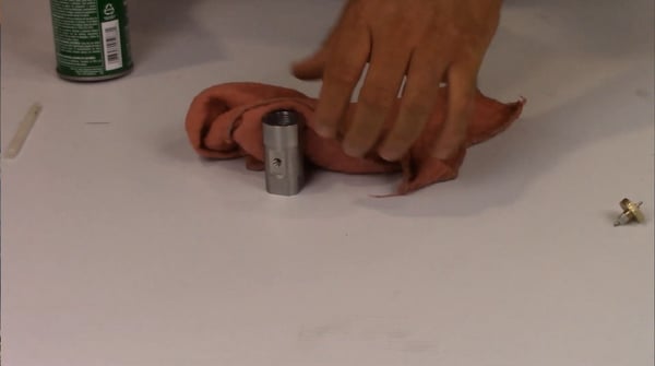
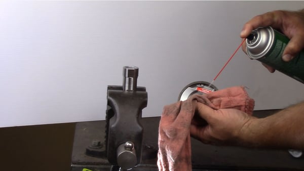
- Clean off the air valve and remove any debris.
- Apply precision lube to the air valve threads of the air valve.
- Securely tighten the air valve to the valve body.
- Tighten on the bench using the same two wrenches you used to loosen in step 14.
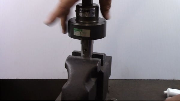
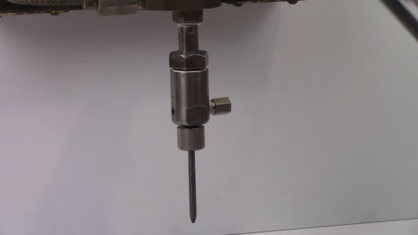
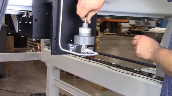
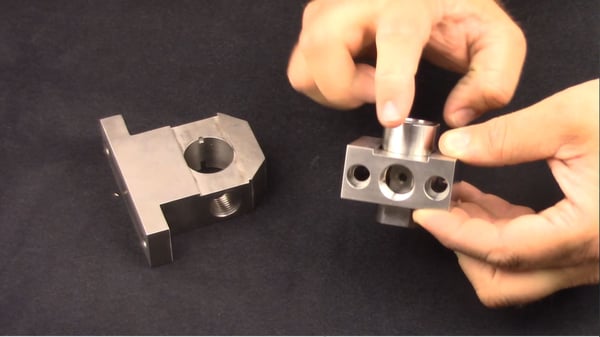
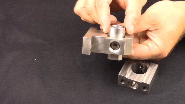
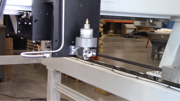
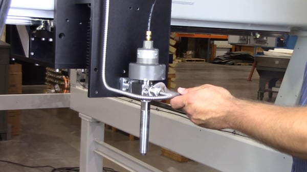
- Bring the OmniJet back to the machine and insert into the mounting collar.
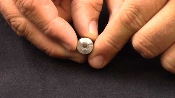
- Check both the tapers of the cone for damage and pitting. Replace the bullet in the inlet adapter if necessary.
- Thread the inlet adapter into the mounting collar having the cone angle make contact with the inlet of the valve body.
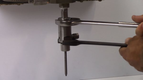
- Tighten the inlet adapter to the head using a 13/16th
- Tighten airline connection and turn on air.
- On the controller, enable the cutting head to apply air to the OmniJet.
- NOTE: Turning on the air allows the air valve to open and the needle to travel upward into the seat. Failure to do so will cause system damage.
- NOTE: If using a Permalign II, install the seat on the top the adapter, note the orientation.
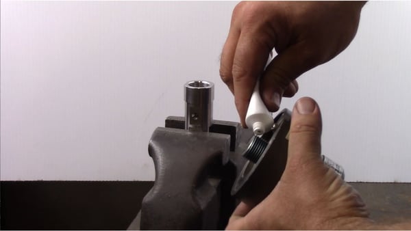
- Use precision lube on the contact points of the seat and the threads of the adapter.
- Install the part into the valve body.
- Using two wrenches, tighten the adapter to the valve body connection.
- Turn the abrasive body to the correct location for the abrasive line connection.
- Once in the correct orientation, tighten the nut to the abrasive body using the same wrenches you used in step 2.
- Connect the abrasive line now.
- IF USING A WATER ONLY MOUNT:
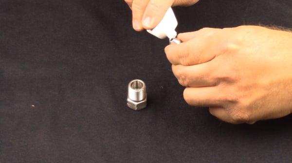
- Install the seat onto a clean orifice mount, noting orientation.
- Apply precision lubricant to the threads and the contact points of the seat.
- Tighten using the same wrenches you used in step 5a.
- Install the seat onto a clean orifice mount, noting orientation.
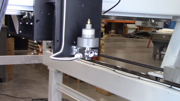
- Install ultra-high-pressure tubing on the cutting head applying precision lube as necessary.
- Tighten the line connection.
- Open the hand valve to allow ultra-high-pressure water flow to the cutting head.
- Disable the cutting head and remove locks from the pump.
Flush the Lines
- Always flush your lines after working on any component of the high-pressure water system.
- For a full guide on flushing the HP water system, click here: https://blog.jetedgewaterjets.com/water-jet-pumps/pump-maintenance-series-part-4-flushing-high-pressure-water-system
The Benefits of Maintaining Your Water Jet Pump
The primary point of all pump maintenance is the high-performance operation of your water jet system. Keeping the pump maintained will allow maximum performance during cuts for the lifetime of your system. Failing to properly maintain your cutting heads during the life of your system can not only cause additional wear and failure of the system, it’s also a significant safety hazard. This is particularly true if the needle seat has failed and water is leaking while the system is off.
Regular maintenance intervals are key to keeping your machine always running. Downtime is costly, and regular maintenance significantly reduces the total downtime of your cutting system.
Check Out Our Digital Brochure!
Since 1984, Jet Edge has been designing and manufacturing Ultra-High-Pressure Water jet technology that doesn't back down. Our systems are used around the world in a broad range of industries from the world's leading airlines, to automotive, aerospace and industrial manufacturers, and machine job shops.
To learn more about the Jet Edge difference, our water jet motion systems, pumps and much more, click the button "Download Brochure" to get it now!

%20-%20Jet%20Edge%20Waterjets.png "A Blog About our Blog Button (revised) - Jet Edge Waterjets")


