The objective of surface detection is simple: maintain the required standoff distance (SOD) between the cutting head’s nozzle tip and the stock’s surface across the entire cut path regardless of material flatness and surface irregularities. The cutting surface of most materials will vary because they will not have been machined flat prior to cutting to ensure perfectly level surfaces.
The reason why controlling the SOD matters is also simple. If the cutting head maintains a flat path and doesn’t account for surface variations, the SOD will vary across the cutting surface. Depending upon the distance variation, cut quality will be impacted as the width and pressure of the water jet at the point of contact with the material changes as the surface distance changes. This variation is unacceptable when machining materials with tight tolerances.
With water jet cutters, there are two main surface detection approaches to controlling SOD: contact and non-contact. Both have their pros and cons. For this article, we will look at non-contact surface detection using laser surface mapping.
More About Standoff Distance (SOD)
The optimal SOD depends on the type of cutting being performed, the material being cut, and the desired cut quality. As a starting point, the optimum SOD guidelines for the highest cut quality suggest:
- 3-axis abrasive water jet cutting SOD: 0.125” - 0.250”.
- 5-axis abrasive water jet cutting SOD: 0.125”
To ensure a consistent cut finish through the entire cut cycle, the SOD should be consistent at each point along the cut path, adjusted to account for surface irregularities. Cutting too close to the material can cause back pressure, clogging the abrasive line. In the worst-case scenario, the nozzle directly contacts the stock, which can easily damage the cutting head and other components.
An SOD that is too high can cause cut quality problems if the spray pattern enlarges and the delivered cutting pressure is reduced with the extra distance.
As you can imagine, providing this information to the cutting process is vital to cut quality and equipment safety. Fortunately, laser surface mapping simplifies this complex task.
⚠️ WARNING: Most lasers used in surface mapping are typically Class 2, Class 3R, or Class 3B, depending on their intensity and application. Direct exposure to the beam can be hazardous to the eye, and diffused reflections may also pose a risk. ALWAYS wear protective glasses and NEVER look directly into the laser.
What is Laser Surface Mapping?
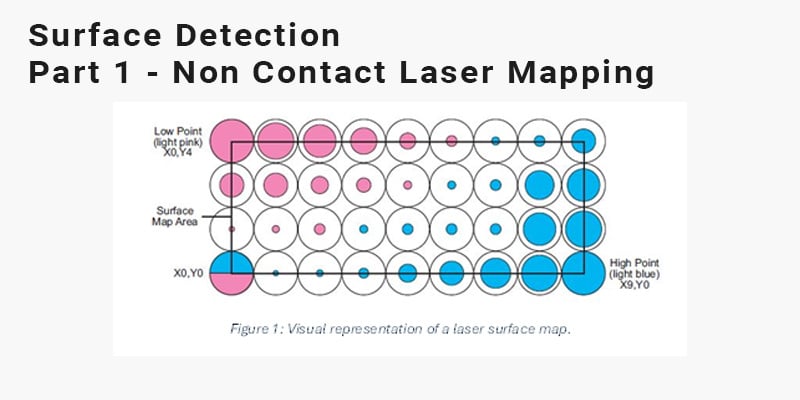
Have you ever seen a LiDAR (light detection and ranging) scan of a piece of terrain? The results are remarkable and produce incredibly detailed 3-D models of the topography. Laser surface mapping used in water jet systems uses a similar concept. The stock material is set up on the cutting bed, and a laser scans the surface, creating a 100 x 100-point grid containing 10,000 points (Figure 1 seen below). These points are precisely mapped to the material and fed into the control software thus creating a map of surface variations along the cutting path. Once the cutting process begins the program will adjust the SOD as dictated by the laser mapping points

 Most manufacturers will offer a factory-installed surface mapping option with a laser sensor that mounts near the cutting head during mapping operations and is stored in an enclosure with a laser controller during cutting operations (see an example of Jet Edge’s implementation in Figure 2 on the right). When creating a surface map the laser follows a defined serpentine path across the area to be mapped, recording surface variations up to a ±0.6 inch (±15 mm) range. This surface map data is imported into the part program via the controller (an example of Jet Edge’s Aquavision DI software is shown in Figure 3 of this post below this paragraph) and is used to maintain the desired SOD during the cut cycle as surface heights vary.

When Laser Surface Mapping is the Perfect SOD Control Approach
Like any solution, there are times and situations where laser surface mapping performs better than other SOD calculation and control techniques. Here are some of those situations:
- Cutting delicate stock where non-contact detection eliminates the risk of damaging or deforming materials with a contact probe foot.
- Using materials with sudden undulations that a contact height sensor may not ride over.
- Cutting sheet materials that are not prone to springing during the cut or tipping above the material surface.
- Performing bevel and 5-axis contour cuts where a height sensor cannot follow the material shape.
- When viewing the laser-mapped SOD data over the part profile on the control screen assists in material positioning or allows the operator to reject a non-conforming material.
The Limitations of Laser Surface Mapping
There are a couple of limitations to mention for all the benefits of non-contact laser mapping.
- The laser has a detection range ±0.60 inch (±15 mm) range, larger undulations are not detected.
- Once the map is generated, fed into the program software, and the cut begins, the SOD follows the original scan. If the material surface changes during the cutting process, it is not detected and accommodated.
- The technology can seem more expensive and complicated than other SOD control approaches; however, when factoring in the savings in scrap and rework the investment often outweighs the initial costs.
- Your operators must be trained to use the laser and associated software, and your technicians must be trained to maintain and calibrate the laser sensor.
Is Non-Contact Laser Mapping Right for You?
Non-contact laser mapping and SOD control delivers superior results in the suitable applications. Here’s a table summarizing how non-contact and contact SOD technologies perform in different situations.
|
Criteria |
Non-Contact Laser SOD Control |
Contact SOD Control |
|
Best for Material Types |
Highly irregular, or non-flat materials; materials that do not deform during cut |
Thicker, sheet materials; materials subject to spring relief during the cut |
|
Cut Complexity |
Best for advanced 5-axis systems with higher-precision needs |
Ideal for simpler, lower-complexity cuts on 3-axis systems; low contoured 5-axis cutting from plate |
|
Dynamic Adjustment |
SOD adjustments are not dynamically made after the cut begins |
SOD adjustment is made in real time as material shape changes |
|
Surface Characteristics |
Works best with shapes and surfaces that allow uninterrupted laser reflection; material would be damaged by pressure foot |
Gradual gradient surface variations are preferred; surfaces that will not be damaged due to contact with the probe foot |
|
Impact on Cut Speed |
No impact on cut speed as SOD is programmed into file |
Often a slower federate is used due to the physical contact of probe |
|
Risk of Interference |
Changes to the hold down method post scan, parts that have tipped and material that springs during the cut will not be detected |
Hold down clamps/ fixtures in the cut path may be hit and cause damage. |
|
Maintenance |
Laser must be kept clean and stored securely in its enclosure during cut |
Higher mechanical maintenance on foot due to wear from contact; requires occasional recalibration per above |
|
Cost |
Higher initial investment but potentially greater efficiency |
Lower upfront cost but some ongoing maintenance costs over time |
Talk to Jet Edge About Surface Detection Solutions
Maintaining a precise SOD during the cutting and machining process is vital to producing consistent edge finishes and cut accuracy through the entire cut. Using surface detection methods, you also can avoid the damage associated with coming into contact with material or fixtures during the cut. Just another way Jet Edge focuses on contributing to a solid bottom line by improving productivity and reducing scrap loss.
If you haven’t added surface height detection capability to your water jet machining process, we encourage you to investigate how it can help your operations today. Our engineers love talking to customers and helping them select the best water jet solutions.
Visit our Blog Library and Comprehensive Video Collection
Jet Edge offers a comprehensive library of maintenance training videos, case studies, best practice blogs and a whole lot more in our resource center.
If you would like to learn more about Jet Edge Water jet Systems, visit us online at jetedgewaterjets.com. If you are ready to speak with your regional expert, just let us know on our contact us page, or call us toll-free at 1-800-JET-EDGE (538-3343), internationally at +1-763-497-8700.
Check Out Our Digital Brochure!
Since 1984, Jet Edge has been designing and manufacturing Ultra-High-Pressure Water jet technology that doesn't back down. Our systems are used around the world in a broad range of industries from the world's leading airlines, to automotive, aerospace and industrial manufacturers, and machine job shops.
To learn more about the Jet Edge difference, our water jet motion systems, pumps and much more, click the button "Download Brochure" to get it now!



%20-%20Jet%20Edge%20Waterjets.png)


