Your water jet is a precision, high-performance, high-volume industrial cutting and machining tool. As such, proper installation is a necessity if you want to maximize the tool’s performance, quality, and longevity. And the foundation for a proper installation is thorough, detailed site preparation.
Why is site preparation so important and impactful on the water jet's performance and service life? If you do not do site prep the right way, you may face the following issues:
- Operational headaches
- Downtime during installation
- Reduced component life
- Increased maintenance costs
- Safety risks
To help you pull off the perfect site preparation project, we’ve summarized our best-practice recommendations in this introduction blog. For our more complete 30+ page guide, please contact our team and we’d be happy to provide the document as well as additional assistance.
Space & Layout Planning: Start with the Footprint
When considering the space required for your new water jet system, there are 3 essential elements to consider:
- The size of system components
- Requirements for proximity between various components
- Space needed to safely operate and maintain these items
For the first and second elements, Jet Edge can provide the detailed information based on your specific system configuration. For the 3rd element, this will be a combination of Jet Edge input and your own needs. Below are some specific points to consider:
- What is the largest size of stock you plan to cut? Allow room to get it to the water jet, load it on the cutting table, and unload the cut parts.
- Allow for minimum safe distances as required by OSHA, State and Local safety requirements, and your own SOP.
- While height isn’t a common concern in a typical industrial machining setting, clear height for high-pressure whips and other devices should be validated.
- Ensure you have ample space for maintenance (likely accomplished with safe operating clearance decisions).
Equipment Footprint Considerations
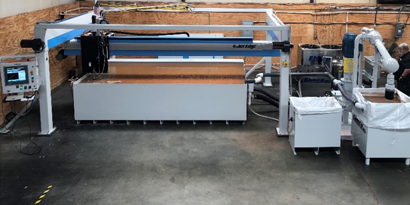
The typical water jet cutting system is comprised of the following pieces of equipment:
- Motion control system, i.e. mid-rail or high-rail machine
- Catch tank
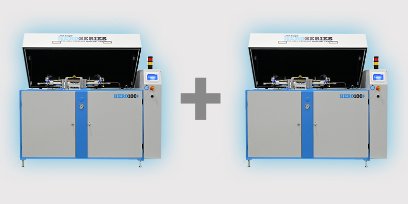
- Intensifier pump
- Bulk hopper (for abrasive cutting systems)
- Optional Water filtration & ancillary equipment
The diagram below provides one possible footprint for a mid-rail water jet cutting system.

Equipment Footprint Considerations
While physically independent items, the motion control system and catch tank generally have a very specific and fixed alignment requirement, per the system design. Consider these as a single unit from a physical layout standpoint, where other items placement is relative to this base unit. Below is a summary of options for some of the other items. For all pieces of equipment, consider the necessary utility supplies:
-
Intensifier Pump – there is some flexibility to both the location and proximity of the pump to the motion system. Considerations include incoming water supply, routing of ultra-high-pressure water lines (from pump to system). It should be noted that it is possible to place this unit quite a distance from the motion system (several hundred feet), there can be implications regarding pressure drop, etc. that should be reviewed with Jet Edge.
-
Bulk Hopper (required for abrasive cutting) – There is some flexibility about placement of the Bulk Hopper – considerations include ease of access for abrasive filling (whether manual, or via forklift), and length and route for abrasive delivery hose to connect to the motion system.
-
Abrasive Removal System (optional) – if your system is equipped with an abrasive removal system, this unit is generally required to be quite close to the motion system. There are a few orientations with which this unit can be placed, but to ensure maximum efficiency of operation, any suggested non-standard locations for this unit need to be carefully reviewed and approved by Jet Edge.
-
Chiller (optional) – the chiller should generally be located near the Intensifier Pump, but the specific layout is flexible. In some space constrained operations, customers have elected to mount chillers on an elevated platform, e.g. above another piece of equipment, which can be a good solution.
-
Closed-Loop Filtration System (optional) – like the chiller, these units should also generally be located near the Intensifier Pump, but the specific layout is flexible.
-
Settling Weir (optional – required with CLS) – the settling weir unit should generally be located near the catch tank, but there is some flexibility to specific location.
For all of the above, the general theme is that quite a bit of layout flexibility exists. We have seen customers use MANY different approaches to machine layout and are ready to provide seasoned guidance on what we believe will work best for your unique situation and why.
Structural & Environmental Requirements
Floor Load
Water jet systems are substantial pieces of equipment, engineered and manufactured to withstand the rigors and punishment of high-volume, continuous use. That means the best ones are designed with thick-gauge steel structures and heavy-duty components throughout. And while the machinery itself is substantial, when accounting for the weight of the water in a full catch tank, the entire system can easily be in the 10-30 Ton range or higher, depending on size. This is a very substantial per-square-foot load.
It is important to consider if your facility’s floor can support the weight of your water jet. You may need to consult the construction plans and specifications for your facility, and in some cases, a structural engineer may be called upon to evaluate the load-bearing capacity of the location where you plan to place your water jet.
Operating Environmental Conditions
Water jet cutting systems operate at their best under specific environmental conditions. Below is brief list of items to consider:
- Relative humidity:
- Must be non-condensing. Recommended maximum of 95% at 95° (35°C).
- Ambient temperature:
- For standard open-loop cooling (cooling water flows to the drain), the ambient temperature must be within 50°-95 ° F (10°-35° C).
- Optional closed-loop chillers provide supplemental cooling (chilled, recirculating cooling water). When the ambient temperature ranges between 95°-110° F (35°-43° C), the chiller capacity is reduced by 1% per 1° F; when the temperature ranges between 110°-120° F (43°-49° C), the capacity is reduced by 2% per 1° F.
- Heat load management:
- Depending on your operating condition, you may need to manage heat load generated by the intensifier pump and / or input into the cutting tank.
If your operation cannot meet these environmental conditions, special accommodations may be needed, or there may be an impact to operation and maintenance requirements.
Water Jet Electrical Requirements: Powering the System Correctly
Dedicate an Electrical Circuit to Your Water Jet System
 We recommend connecting your water jet to a properly sized, protected, dedicated electrical circuit. A dedicated circuit isolates the water jet from interference induced by other equipment operating on the same lines. As that equipment starts and stops, it can create dips, spikes, and voltage variations that can affect the water jet, and not in good ways.
The most important consideration is that all electrical supply and connections must comply with local building codes, the NEC and OSHA requirements. In the unlikely event you encounter a local code that conflicts with our requirements, contact us for assistance.
Depending on your stability of local electrical supply, it may also be worth considering adding power conditioning to ensure your water jet receives clean, stable power with a constant voltage and frequency. If you’re concerned, it’s a good topic to discuss with your electric company. A power blink or voltage sag can cause unintended affects that might lead to scrapped parts and loss of productivity.
Access and Serviceability
As we mentioned, your electrician must install electrical circuits, panels, and protection devices in accordance with local codes. Jet Edge requires that all doors on all electrical panels and boxes be able to open a full 90°, and recommends that junction boxes be included at the rear of the motion table and the intensifier pump.
Considering Your Water Supply
Another important factor to consider is the quality of your water supply, which may have an impact on the performance of the system and the service life of certain consumable and wear items.
Let’s take a look at what you need to account for in your planning.
Water Requirements
A good first step is to have a professional water-quality analysis performed by a commercial company specializing in water-conditioning equipment. To aid them in their recommendations, provide them with these quality requirements:
- TDS: 5–200 mg/L acceptable range
- pH: 6.5–8.5
- Silica: ≤14 mg/L
- Chloride: ≤15 mg/L
- Iron: ≤0.2 mg/L
The company will compare the test results to these values and provide you with a recommended solution. Technologies commonly used to control water quality include:
- Water Softening
- Reverse Osmosis (RO)
- Deionization (DI)
- Filtration
We have a detailed blog post on water conditioning that provides much more information.
Water Uses
Depending on the configuration of your system, water may be consumed for both cutting (process water) and cooling.
Cutting
The intensifier pump requires pretreated water to maximize the longevity of system components. High pressure seals, check valves, and orifices can be affected. In some cases, water quality issues can prematurely age other high-pressure components like tubing, cylinders and other items.
Cooling
While the heat exchanger can operate on your tap water supply, depending on tap water quality, it may be a good idea to supply it with pretreated water as well to prevent impurities from reacting with the copper in the exchanger, which can shorten its lifespan.
Recommended cooling water specifications are:
- 3–12 GPM flow depending on your pump
- Max 70°F inlet temperature (cooler is better)
- Minimum 40 psi pressure
Temperature considerations: Depending upon where your facility is located and whether you are drawing water from a municipality, well, or surface source, you may need to adjust the incoming water temperature. Supplemental chillers are common in warmer climates.
We encourage you to read our blog on the topic to learn more about:
- Open and closed loop chillers
- The role of heat exchangers
- When should supplemental cooling be used
Compressed Air Requirements
Water jet systems use compressed air for several key tasks, such as on/off control, managing abrasive feed systems, and powering the catch tank bladder option. In particular, it is important to provide a continuous supply of dry, filtered air to the motion control table and the dense phase hopper, as moisture in the compressed air can cause issues with abrasive flow.
Plan Once, Cut with Confidence
You know the old saying that goes, “Measure twice, cut once,” right? Well, when it comes to getting the most out of your new water jet, the adage becomes, “Plan once, cut with confidence.”
Remember what a thorough site preparation plan accomplishes:
- Supports operational efficiency and safety
- Improves ease and safety of maintenance activities
- Maximizes floorspace efficiency
- Reduces downtime and enhances component lifetime – maximizing productivity and profitability!
Of course, we are here to support you every step of the way. Contact us online or call today at 1-800-538-3343 (US) or +1-763-497-8700 (Internationally). We look forward to helping you.

Check Out Our Digital Brochure!
Since 1984, Jet Edge has been designing and manufacturing Ultra-High-Pressure Water jet technology that doesn't back down. Our systems are used around the world in a broad range of industries from the world's leading airlines, to automotive, aerospace and industrial manufacturers, and machine job shops.
To learn more about the Jet Edge difference, our water jet motion systems, pumps and much more, click the button "Download Brochure" to get it now!


%20-%20Jet%20Edge%20Waterjets.png "A Blog About our Blog Button (revised) - Jet Edge Waterjets")


