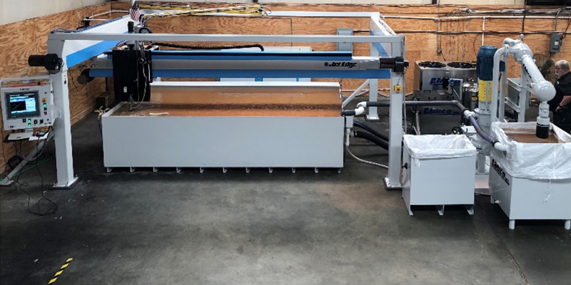
Water jet systems are among the most versatile tools in modern manufacturing, offering precision cutting for an extensive range of materials. One minute, you can cut stainless steel with 60-degree bevels and then quickly change over to cutting glass, plastic, foam, composites, and a host of other materials using the water-only cutting capability of your tool. In fact, by utilizing a Spreader Bar with a 3-axis high rail system, up to 12 abrasive and / or water-only cutting heads can be mixed for maximum productivity. Talk about flexibility!
As with all production operations, properly optimizing application parameters for water-only cutting is key to maximizing production efficiency and cost-effectiveness. This starts with selecting the right water-only orifice for your water jet machine. Let’s explore.
Why the Orifice Matters

The water-only orifice is the unsung hero of your water jet system. It is responsible for focusing the ultra-high-pressure (UHP) water supplied by the intensifier pump into a concentrated, cohesive stream that will perform the cutting operation. This stream's precision impacts everything—from cutting accuracy to part quality to overall process efficiency and operating costs.
Additionally, the size (inner diameter, “I.D.”) of the orifice defines the amount of water (measured in gallons per minute, “GPM”) that the cutting head will use. This in turn impacts the cutting process as well as defining the number of cutting heads that can be supported by a given pump. Choosing the right orifice material and size ensures:
- Optimal Cut Quality: Prevents chipping and rough edges.
- Production Efficiency: Maximizes throughput without compromising accuracy.
- Cutting Precision: defines cutting resolution for fine features.
- Consumable Longevity: Reduces wear on consumable components, increasing intervals between maintenance and minimizing downtime.
Anatomy of a Water-Only Cutting System
A water-only cutting system relies on precisely coordinating your water jet’s components to achieve its performance. Here’s how it all works:
- UHP Water Control Valve: This air-actuated valve controls the on/off modes for the water flowing through the cutting head, as dictated by the cut's programming parameters.
- Orifice Material: Determines durability and lifetime performance.
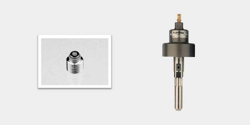
- Orifice Mount: Properly seats the orifice and ensures optimal water jet alignment to the cutting surface. Correctly aligned and seated orifices produce a jet of water that looks like a fishing line. This arrangement differs from the use of a nozzle in abrasive cutting.
Check out our sister post to this blog about abrasive cutting nozzle/orifice combos by clicking here.
Orifice Material Choices - Selecting the Right One for Your Needs
 Water-only orifices are crafted from robust materials designed to handle the enormous pressure generated by the intensifier pumps that power these UHP systems. The orifice’s housing is constructed from stainless steel for durability and water resistance. At the heart of the orifice body is the hardened material (the jewel) through which the orifice inner diameter (I.D.) focuses the water jet into the cutting stream. Orifices are classified by their jewel material and I.D. size.
-
Sapphire and Ruby Orifices:
- Advantages: Cost-effective and suitable for light-duty applications, these two gems are equivalent from a performance and cost standpoint.
- Disadvantages: These gems have a high rate of wear combined and increased risk of chipping and or cracking, leading to relatively short overall component lifespan.
-
Diamond Orifices:
- Advantages: Natural diamond orifices are the top of the line when it comes to overall performance. The gem has incredible wear resistance properties, and the housing uses a protective carbide backer to increase lifetime of the mount. They are increasingly popular in high-volume shops as well as for heavy-duty applications due to their reliability, significantly longer life, and lower operating costs per hour over their lifetime.
- Disadvantages: More expensive unit cost than sapphire / ruby or synthetic diamond options.
- Advantages: Natural diamond orifices are the top of the line when it comes to overall performance. The gem has incredible wear resistance properties, and the housing uses a protective carbide backer to increase lifetime of the mount. They are increasingly popular in high-volume shops as well as for heavy-duty applications due to their reliability, significantly longer life, and lower operating costs per hour over their lifetime.
Key Factors in Selecting the Right Orifice
At a given working pressure, the orifice size will determine the flow rate of water used by the cutting head. Based on the horsepower of your intensifier pump, there will be a maximum volumetric flow rate of water it can supply. Choosing the ideal orifice for your operation and the materials you routinely cut involves evaluating the following:
- Operating Pressure: Your pump’s maximum pressure rating determines the orifice’s performance capabilities.
- Flow Rate: Measured in gallons per minute (GPM), this influences cutting speed and precision.
- Application Needs: Consider the type and thickness of materials you frequently cut.
- Number of Cutting Heads: Adjustments may be needed when running multiple heads simultaneously.
Using the Orifice Sizing Table
Follow these steps to determine the maximum allowable orifice size from the table below:
- Choose the operating pressure (psi) column the pump will be set to for the cut
- Work down the operating pressure (psi) column until you arrive at the highest pump flow rate (gpm) that does not exceed the rating of the pump you are utilizing
- The value in the leftmost column is the maximum orifice I.D. that can be used
Operating Pressure (psi) & Flow Rates (gpm)
|
Orifice I.D. (Inches) |
Operating Pressure (psi) x 1,000 |
|
||||||||
|
20 |
25 |
30 |
35 |
40 |
45 |
50 |
55 |
60 |
|
|
|
0.010 |
0.30 |
0.33 |
0.36 |
0.39 |
0.42 |
0.44 |
0.47 |
0.49 |
0.51 |
Pump Flow Rates (gpm) |
|
0.011 |
0.36 |
0.40 |
0.44 |
0.47 |
0.51 |
0.54 |
0.57 |
0.59 |
0.62 |
|
|
0.012 |
0.43 |
0.48 |
0.52 |
0.56 |
0.60 |
0.64 |
0.67 |
0.71 |
0.74 |
|
|
0.013 |
0.50 |
0.56 |
0.61 |
0.66 |
0.71 |
0.75 |
0.79 |
0.83 |
0.86 |
|
|
0.014 |
0.58 |
0.65 |
0.71 |
0.77 |
0.82 |
0.87 |
0.92 |
0.96 |
1.00 |
|
|
0.015* |
0.66 |
0.74 |
0.81 |
0.88 |
0.94 |
1.00 |
1.05 |
1.10 |
1.15 |
|
|
0.016 |
0.76 |
0.85 |
0.93 |
1.00 |
1.07 |
1.13 |
1.20 |
1.25 |
1.31 |
|
|
0.017 |
0.85 |
0.95 |
1.05 |
1.13 |
1.21 |
1.28 |
1.35 |
1.41 |
1.48 |
|
|
0.018 |
0.96 |
1.07 |
1.17 |
1.27 |
1.35 |
1.43 |
1.51 |
1.59 |
1.66 |
|
|
0.019 |
1.07 |
1.19 |
1.31 |
1.41 |
1.51 |
1.60 |
1.69 |
1.77 |
1.85 |
|
|
0.020* |
1.18 |
1.32 |
1.45 |
1.56 |
1.67 |
1.77 |
1.87 |
1.96 |
2.05 |
|
|
0.021 |
1.30 |
1.46 |
1.59 |
1.72 |
1.84 |
1.95 |
2.06 |
2.16 |
2.25 |
|
|
0.022 |
1.43 |
1.60 |
1.75 |
1.89 |
2.02 |
2.14 |
2.26 |
2.37 |
2.47 |
|
|
0.023 |
1.56 |
1.75 |
1.91 |
2.07 |
2.21 |
2.34 |
2.47 |
2.59 |
2.70 |
|
|
0.024 |
1.70 |
1.90 |
2.08 |
2.25 |
2.40 |
2.55 |
2.69 |
2.82 |
2.95 |
|
|
0.025 |
1.85 |
2.06 |
2.26 |
2.44 |
2.61 |
2.77 |
2.92 |
3.06 |
3.20 |
|
|
0.026 |
2.00 |
2.23 |
2.44 |
2.64 |
2.82 |
2.99 |
3.16 |
3.31 |
3.46 |
|
Table Notes and Examples
*For Example, the flow rates provided in the table above are for a single orifice. A 50 hp pump operating at 55k psi, capable of producing 1.10 gpm, could utilize an orifice with an I.D. of up to .015 inch. A 100 hp pump operating at 55k psi, capable of delivering in excess of 1.96 gpm, could be used with a .020 inch I.D. orifice.
When a multiple-orifice setup is used, the total flow rate must be calculated by adding the individual flow rate for each of the orifices. For example, a motion system using four 0.010” orifices at 55k psi requires a flow rate of four times 0.49 GPM, or 1.96 gpm total.
Choosing an orifice with too large an I.D. effectively asks the pump to deliver a greater water flow rate than it is rated for. This creates what is known as an over-cycle condition where the piston attempts to cycle too fast. The pump PLC senses this event and shuts down the pump to prevent unwanted wear and tear. While technically there is no minimum orifice size that can be used, it is unusual to see sizes below 0.005”.
Practical Tips for Operators
- Always consult the manufacturer’s Orifice Sizing Table to match your pump’s capabilities and desired performance metrics.
- Smaller orifice diameters are best for intricate work on delicate materials. For heavy-duty cutting, larger diameters resulting in higher water flow rates may be more effective.
- Regularly inspect orifice mounts for wear or misalignment that could compromise jet cohesion.
Selecting Your Orifice Mount
The orifice mount attaches to the UHP water control valve on the water-only cutting head assembly and acts as a length extender to define the location of the actual orifice. The length of the orifice mount affects the length of the water stream core and impacts how fast the water stream can be turned on and off.

The longer mount delivers a more accurate cut and is preferred for cutting thicker materials more accurately and to a higher finish, however, it increases the dwell time required to fill the internal volume of the mount and hence the time required to turn the stream on and off. A short orifice mount length reduces that dwell time and shortens the on / off portion of total cycle time. This may be more impactful for applications with high on / off frequency and relatively short pierce and cutting time. A “standard” program uses a dwell time of .5 seconds in a program before it starts moving after the call to open, and the call to close (1 second total). If you use a shorter mount body, you can cut this time by .5 seconds.
Balancing Efficiency and Costs
Operational efficiency involves balancing speed, quality, and consumable costs. Testing and data tracking are essential for identifying the most cost-effective setups.
Use the following metrics for evaluation:
- Cutting Rate/Feed Rate: Measured in inches per minute, this metric tells you the speed and time needed to complete cuts on various materials.
- Precision: Accuracy / repeatability required for cut features.
- Surface finish / Quality: desired smoothness or allowable roughness of cut edge, impacted by material type and thickness.
- Consumable Longevity: Lifespan of orifices and other components.
Material properties, such as material type, hardness, thickness, composite structure, and porosity, must be considered when selecting the water-only orifice size, mount length, and configuration. The best way to determine the ideal orifice/mount combo for a given application is to build a Cutting Rate Table.
To do this, begin a series of test cuts on your material using a range of orifice and mount combinations at various water pressures and cut speeds. Create a table to record the results and use your data to select the optimal combination for your application. A simple example of this is illustrated below.
|
Material Type |
Material Thickness (in) |
Orifice / Nozzle Combination |
Water Pressure (PSI) |
Cut Speed (IPM) |
Observations / Results |
|
|
|
|
|
|
|
|
|
|
|
|
|
|
|
|
|
|
|
|
|
|
|
|
|
|
|
|
Troubleshooting Common Issues
Even with the proper setup, issues can arise for a variety of reasons. Here are a few common problems and their solutions:
- Loss of Cut Quality: Check for debris in the orifice. This can be particularly problematic for smaller I.D. orifices that are common for water-only applications. One effective solution is to utilize a short stop filter that can prevent such debris from reaching the on / off valve and orifice.
- Uneven Cuts or Loss of Cut: Inspect the high-pressure pump for proper performance. Ensure cutting feed rate is correct for material type and thickness.
- Excessive Wear: Ensure proper installation of the orifice and consider utilizing diamond orifices for increased wear life.
Got a Tough Cut?
When faced with challenging projects, don’t hesitate to seek expert guidance. Jet Edge’s application engineers specialize in helping clients optimize their setups for unique cutting needs. Contact us to discuss your materials, project specifications, and issues, and we’ll recommend the best solutions.
Explore More in Our Blog Library and Comprehensive Video Collection
We’ve packed Jet Edge’s Resource Center with valuable insights to enhance your operations, including solutions for everyday challenges, strategies to improve cutting efficiency, and tools to maximize system longevity, including:
- Maintenance and training videos.
- Case studies showcasing innovative solutions.
- Best practices blog for maximizing water jet performance.
Ready to elevate your water jet cutting capabilities? Speak with one of our regional experts today by calling 1-800-JET-EDGE (538-3343), +1-763-497-8700 internationally, or visiting our website.

Check Out Our Digital Brochure!
Since 1984, Jet Edge has been designing and manufacturing Ultra-High-Pressure Water jet technology that doesn't back down. Our systems are used around the world in a broad range of industries from the world's leading airlines, to automotive, aerospace and industrial manufacturers, and machine job shops.
To learn more about the Jet Edge difference, our water jet motion systems, pumps and much more, click the button "Download Brochure" to get it now!


%20-%20Jet%20Edge%20Waterjets.png "A Blog About our Blog Button (revised) - Jet Edge Waterjets")


